Gas/Solid Cyclone - Technical Information
Cyclones are commonly used for the recovery of fines from air and process gases. Due to the increasing number of emissions regulations, the efficiency of cyclones is a major concern.
The cyclone separator can simulate the separation of solid phase material with a particle size distribution from vapor streams.
Calculation Method
The cyclone separator model can determine the efficiency of solids removal using one of three different efficiency methods: those developed by Lapple, by Koch and Licht, and by the American Petroleum Institute (API).
You must select Design or Rating calculations. In rating mode, you must specify diameter, inlet height, inlet width, etc. The rating mode will calculate efficiency of multiple cyclones in series or in parallel, bu the cyclones must be of identical size. In design mode, you must specify an efficiency and the diameter of the cyclone will be calculated. The result may dictate multiple cyclones. You may specify if the multiple cyclones will be configured in parallel or series. Maximum pressure drop across all cyclones in the unit may be specified in design mode.
Pressure drop calculations may be carried out using either the method presented by Koch and Licht or by the API. The Koch and Licht method yields a conservative estimate of the pressure drop since it assumes a gas-only feed. An adjustment to the pressure drop to account for high solids loading is applied to the Koch and Licht method if the solids loading is within the applicable range. The API method is recommended only for solids loading greater than 4 pounds of solids per second per square foot of inlet area. A setting is available in the cyclone to automatically switch from one pressure drop method to another based on the solids entering the cyclone (e.g. as the loading changes in series cyclones).
Cyclone Geometry
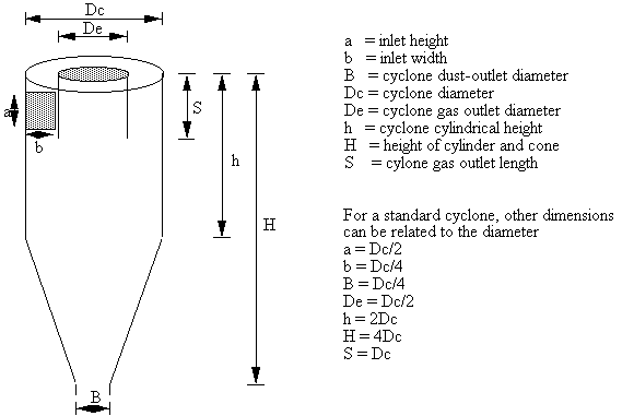
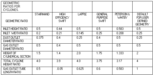
Many standard geometries can be specified. Alternatively you may specify a custom geometry by providing the diameter of the cyclone cylinder and the inlet height ratio (with the cyclone diameter), inlet width ratio, cyclone dust outlet diameter ratio, cyclone gas outlet diameter ratio, gas outlet tube length ratio, height of cylindrical section ratio, and total cyclone height ratio as required by the calculation method.


TABLE 1. GEOMETRIC RATIOS FOR CYCLONES.
In addition, you may specify whether an inlet vane exists and the shape of the gas inlet.
Cyclone Inside Vessels
If you specify that the cyclone is inside a vessel, then you must also provide the diameter of the vessel that houses the cyclone and the superficial gas velocity. The dipleg diameter will be calculated.
Feed and Product Streams
The cyclone unit can have up to 10 feed streams. The inlet pressure is taken to be the lowest pressure of all the feed streams, or you may specify the inlet pressure or the pressure drop between the feed stream and the inlet. Liquid feeds are not allowed and all solid components must have particle size distribution data.
Both an overhead and bottoms product streams must be specified. The bottoms contains the solids that are removed from the vapor and solid feed stream. The overhead contains a vapor stream with solids that were not removed by the cyclone.
Solid Components
Particle size distribution of each component is limited to 31 cut sizes (30 size ranges). All solid components entering the cyclone must have a PSD defined.
Additional information
For additional information regarding the use of PRO/II's Gas/Solid Cyclone, please see the PRO/II User's Guide.
Nguyen, T.K., et.al. Development of a Cyclone Unit Operation Model - Final Report, Engineering Interdisciplinary Clinic, California State Polytechnic University, Pomona, CA, June 1995.
![]()
Related Topics