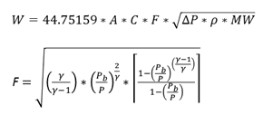
PRO/II software will select the flow equations based on the flow conditions.
If Pcf>Pb then sonic flow equations will be selected.
If Pcf<= Pb then subsonic flow equations will be selected.
Where

Pcf = Critical flow nozzle pressure
P1 = Upstream relieving pressure
Once the flow changes from Sonic to Subsonic, it always remains subsonic.
For Liquid Only Systems:
Sonic Flow:

Subsonic Flow:
![]()

![]()
Where,
![]() = Ratio of specific heats (Cp/Cv) for an ideal gas at relieving temperature.
The ideal gas specific heat ratio is independent of pressure. Most process
simulators will provide real gas specific heats which should not be used
in the above equation because the real gas specific heat ratio does not
provide a good representation of the isentropic expansion coefficient.
= Ratio of specific heats (Cp/Cv) for an ideal gas at relieving temperature.
The ideal gas specific heat ratio is independent of pressure. Most process
simulators will provide real gas specific heats which should not be used
in the above equation because the real gas specific heat ratio does not
provide a good representation of the isentropic expansion coefficient.
β = Ratio of Orifice Dia to Pipe Dia
For Mixed Phase Systems:
Sonic Flow:
![]()

Subsonic Flow:


More detailed discussions of the various valve models are available in the PRO/II Reference Manual.
Policy
User can provide policy data for Time vs Orifice Area. At different time steps, the appropriate Orifice Area is considered for calculating the flow rates.
Policy grid can be accessed by selecting Policy radio button. By default, Orifice Area radio button is always selected.
![]()
Related Topics